Oiling has been conventionally made by contact system
(brushes, rollers, pads) or spraying system (airspray or
airless spray).
Contact systems are always affected by the uneven flatness of the surface which causes uneven film thickness or dry stripes.
Spraying systems are always associated with a more or less pronounced overspray which impairs the deposition rate, polluting in the same time the working site.
Moreover the oil deposited by conventional means is free flowing from the sites of coils severely contaminating storage floors.
In both cases oil consumption is well over the theoretical - often even three or four times as much and the uniformity of the coating obtained is very poor.
ELECTROSTATIC APPLICATION PRINCIPLES
We shortly remember the principles of electrostatics for the readers which are not familiar with this type of application.
Electrical charges of the same name repel each other, electrical charges of opposite name attract each other.
Moreover fluid filaments or drops immersed in a strong electric field undergo the electrostatic pressure and break out in ever smaller electrically charged droplets which repel each other creating a finely atomized fluid mist.
This mist when opposed to an earthed surface is attracted and evenly settles and firmly adheres on this same surface.
In practice the fluid mist is negatively charged and the metal surface is kept at ground potential connecting it to the mass, which is very easily done due to the presence of large metals structures in every process line.
The deposited droplets loose immediately their electric charge so that no evidence of the electrostatic deposition process is left on the coated surface.
The function of the ELETTROSPRAY oilers is purely based on our deep knowledge of the electrostatic principle.
As a result a minumum of energy is used to atomize the oil, through a keen study of every constructive detail to avoid current losses with great advantage for the safety of operation.
The opposite polarities electrostatic charging system we are now proposing as standard avoids over oiling the strip edges and greatly reduces the escape of oil mist from the enclosure pass line windows.
BASIC DESCRIPTION OF AN ELECTROSTATIC OILER
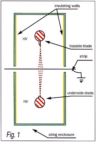
A two blade electrostatic oiler for continuous strips is basically made as follows
(see 1 e 2).
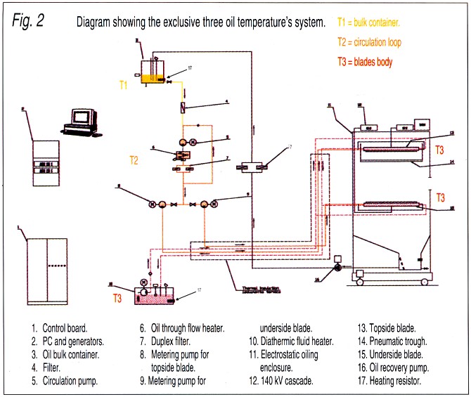
The oil is stoked in a bulk container (3) equipped with a level sensor and a heating resistor (17) to keep the oil at a temperature T1 of 25-30°C sufficient to keep it free flowing all year round.
The oil is gravity fed through a filter to the suction port of our exclusive closed loop circulating system including a pump, a throughflow electric heater and a duplex fine filter. Which such a system a very small quantity of oil is quickly heated to the working temperature T2 of e.g. 60 C° and continuously filtered: due to the small quantity involved the oil stays at high temperature for a very limited time avoiding cracking and consequent decay of its properties and charring off heating resistors. The oil is then fed under low pressure to the metering pumps and sent to the oiling blades which are heated at temperature T3 by circulation of an independent heating fluid.
The oil flow is accurately controlled by the oiler PLC. The output of the metering pumps candy optionally controlled by precision flowmeters mounted downstream of the metering pumps reaching a new standard of precision for this class of machines.
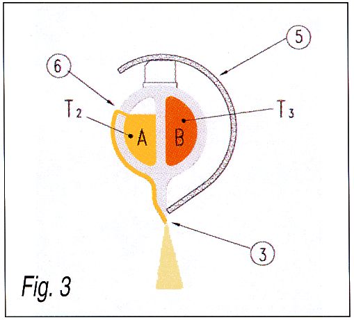
The oil to be applied enters the (A) cavity of the blade and overflows from a range of small holes (6) drilled flow throught the blade wall reaching the shatp edge (3) (Fig.3)
An insulating diathermic fluid is meanwhilecirculated throught (B) cavity keeping the blade temperature at the preset value T3>T2- of e.g. 70-80° C.
In such a way a better viscosity control and costant fine automisation of the oil are obtained.
As it is know when the temperature increases both the viscosity and the surface tension of the oil lower and the atomisation il highly improved.
With this blade design it is possible to apply very viscous products or sometimes products wich are solid at room temperature.
The excess oil (particulary when the strip is narrow compared to the blade length) is collected in a bottom sump provided with levels and then the sucked in by a recovery pump, filtered and recirculated to the storage oil tank.
IThe yield of the oil is therefore near to the theoretical value and there no pollution or effluents treatment problems.
ENCLOSURES
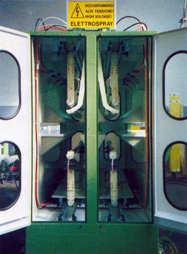
For safety, mechanical protection and good housekeeping the blades are mounted in a suitable enclosure (fig. 4).
The enclosure is provided with clear inspection doors interlocked with the high voltage source and with the oil feeding pumps.
The side walls of the cabin are lined with highly insulating plastic plates wich act as electrostatic refectors.
Special insulating fenders or plates protect the blades against accidental strip impacts.
When single coil instead of continuos strip are to be oiled the enclosure is equipped with a suitable threading table wich makes possible the passage of the strip head through the cabin and then it is automatically retracted or folder down.
Threading tables are normally driven by air cilynders.
When it is not possible to fit on the line a standard enclosure many special designs studied for the special job are available.
Example of special design are enclosures for the Temper mills where very little space is normally available on top of the recoiler, and a very high oil output is requested.
The enclosures can be made stationary or extractable from the line running on suitable rail driven by a brake gearmotor.
ADVANTAGE OF THE ELECTROSTATIC SYSTEM
- Very high deposition rate
- Uniform coating
- Keenly controlled deposited weight
- No pollution
- Total safety
- Big oil savings. At least of 60% over conventional systems
- Reduced maintenance, lacking parts in contact with the strip surface like rolls, pads and the like
- Purely electrostatic process without compressed air nor high pressure involved
- Low energy consumption
- Completely silent run
HIGH VOLTAGE SOURCE
The industrial frequency operated oil filled conventional generators employing selenium rectifiers and big capacitors require strong currents, up to 2 mA. Therefore at the maximum rated voltage of 150kV a 300 W power is involved.
With the most modern electronic generators the same results are obtained employing ma 0.2 mA currents and therefore at a 150 kV max rated voltage a power of 30 W only is involved.
Moreover because of a much lower capacity of the system the energy stored and released in case of a spark is much lower.
The electronic generators are made by a control panel usually mounted into the machine control desk and a "cascade" where the high voltage is generated normally mounted on top of the enclosure.
The shielded high voltage cables are therefore wery short and do not cross the working site with a great safety advantage.
Moreover it is possible to install special automatic earthing device to quicky discharge the residual charges whenerver the generator is turned off.
Using these devices it is no more necessary to discharge the blades from their residual charge with an earthed probe before touching them for maintenance or cleaning.
The provided block and alarm circuits render the use of these generators extremely safe.
We supply a standard two generators, one for each blade to take advantage of the much profitable opposite polarities systeme: drastically reduce oil mist escaping from the enclosure and no overoiling of the strip edges.
ATOMISERS TYPES
We offer now four different electrostaic atomiser types to suit a wide range of application:
| Type : |
Oiling range: |
| Standard Blades |
0.3 - 3.5 g/m2 |
| "Wide range" Slot Blades |
0.02 - 3.5 g/m2 |
| TURBODYN rotating bell units |
2 - 200 mg/m2 |
| PNEUMODYN airspray units |
2 - 5 g/m2 |
The rules of selection are generally flexible and the best type of atomiser fot the application to hand would usually be assed on a one-to-one basis.
In any case oil flows from the atomiser in form of cuspid wich under the effect of the electrostatic pressure break in tiny droplets forming a curtain of very fine oil mist.
Standard blades
The exclusive standard blades are built from a thick walled light alloy extrusion incorporating a blade heating cavity (B) taking 50% of its total inner volume, where in indipendent diathermic fluid is circulated.
The blade edge is formed as a single plane, externally wetted from a row of holes uniformly spaced along the blades body.
There are several advantage with this design.
The orifice dia is about 10 times wider than the conventional slot blade which is virtually self cleaning and mantenance free.
Furthermore, the large heat transfer surface area provides excellent blade temperature control up to a maximum of a 80° C or as suggested by the oil supplier.
The topsite blade is fitted with a non conductive insulating mask to limit the current drain within 50 microAmps.
The atomising edge of the underside blade is twice the length of the topsite blade to ensure the highest possible atomising density and transfer efficiency and is designed specifically to overcome the "flooding" common with conventional slot blades.
"Wide range" steel slot blades
Where it is requested to deposit uniformly low quantities of oil and/or at a very low strip speed we propose the "wide range" slot blades made in high strength steel finely machined and ground to a tight tolerance.
These blades are heated by circulation of an indipendent diathermic fluid through two channels drilled through the two halves of their steel body.
Astonishing performance are obtainable with this type of blades.
TURBODYN rotating bell units
First developed for use as a paint applicator for automotive manufacturers, the system has been modified to apply extremely low oil quantities to ferrous and nonferrous strips. The ELETTROSPRAY TURBODYN atomiser is supplied in the form of a small diameter cup rotated at up to 50,000 revolutions per minute using a mechanically supported turbine. Normally the atomised oil produces a circular pattern on the strip of approximately 600 mm effective diameter, with up to three atomisers positioned each side of the strip. As a first in this field the bells revolutions are electronically controlled. The system is ideal for application of very low coating weights of DOS or similar products normally required on Tin-plate, Black-plate and Aluminium lines.
PNEUMODYN airspray units
Manufactured again by our Elettrospray Division, these atomisers are a development of conventional electrostatic painting guns and may be used for high output applications typical of Temper or Skin-Pass lines or to coat individual sheets immediately ahead of a press. These are ideal tools for use at a typical Temper Mill where there is a big improvement over the conventional contact absorbent roller most often used in this situations and where a very high oil output is required. In every case the atomisers are connected by means of a special High Voltage cable to a HV generator.
AUTOMATION
Each oiler can be provided with full Advanced Automation control, through PLC or additional PC equipment. An Operator Panel displaying status of functions and alarms is supplied as standard. Flow control or monitoring can be provided optionally (but is not considered to be essential to the performance of the machines) and set a new standard of automation in this class of machines. The Advanced Automation system can be interfaced to upper level computers when required via Profibus, Interbus and similar network systems.